Knowing how to select a pneumatic ball valve means matching five things at once — the body material, the seals, the connection standard, the actuator, and the control accessories.. For industrial and corrosive-media service, you are matching five things at once — the body material, the seals, the connection standard, the actuator, and the control accessories — to the job the valve actually has to do. Get one of them wrong and the valve leaks, stalls, or fails to reach position.
At Huiya, our engineers follow the same five-step logic on every enquiry, because it maps cleanly to how a pneumatic (air-actuated) ball valve has to perform in the field:
- Media and temperature → decides the body and seal material
- Pressure and standards → decides the pressure rating and connection
- Actuator type → decides the power source and fail-safe behaviour
- Actuator sizing → decides torque and safety factor
- Signal and feedback → decides the control accessories
This guide walks through each step the way we would walk a customer through it, including the rules of thumb we use internally. It is written for the process and plant engineers who have to make the valve work, and for the buyers who have to specify it correctly the first time.
Step 1: Start with the media and temperature — this decides your body material
The fluid and its temperature drive every other decision, so we always begin here. For thermoplastic ball valves, the body material sets both the chemical compatibility and the temperature ceiling.
| Body material | Max service temp* | Typical media | Common seal pairing |
|---|---|---|---|
| UPVC | ~55 °C | General water treatment, weak acids and alkalis | PTFE seat / EPDM O-ring |
| CPVC | ~90 °C | Hot and cold water, dilute acids | PTFE seat / EPDM or FKM |
| PPH (polypropylene) | ~85 °C | Strong alkalis (e.g. NaOH / caustic soda), inorganic salts | PTFE seat / EPDM or FKM |
| PVDF | ~120 °C | High-concentration strong acids (e.g. 98% sulfuric), halogens (chlorine, fluorine), ultrapure water | PTFE seat / FKM |
*Max temperature is the body rating at ambient pressure. Allowable pressure falls as temperature rises — see Step 2.
If you are not sure which resin your media calls for, our plastic valve material selection guide and our chemical resistance reference compare the four materials side by side. For the most aggressive duties, the PVDF chemical resistance guide lists compatibility against specific acids and halogens.
Choosing the seals
The body resin gets most of the attention, but the seals decide whether the valve actually holds. Two parts matter:
- The seat. On a true union ball valve the seat is normally PTFE by default, so it rarely needs to be specified — PTFE handles frequent cycling without the wear-related leakage that softer seats develop.
- The O-rings. This is where you choose. EPDM is the economical option for water and weak acids and alkalis. FKM (Viton) is the choice for high temperature, strong acids, oils, and halogens, and it is effectively mandatory on chemical lines.
An engineering rule we never break: if the application calls for a PVDF body, we never pair it with EPDM — we standardise on FKM. Any media aggressive enough to justify PVDF has almost certainly already exceeded what EPDM can tolerate, and the cheaper O-ring becomes the first thing to fail.
Step 2: Match the pressure rating and connection standard to your pipework
Plastic ball valves are typically rated PN10 (10 bar / 150 PSI) at ambient temperature, with some configurations available at PN16. The point engineers forget most often: a thermoplastic valve’s pressure rating derates as temperature climbs. A valve that is comfortable at PN10 in cold water may need to be re-rated for hot, pressurised service, so always check the pressure-temperature curve for your operating point rather than the headline figure alone.
The connection has to match your pipe exactly, and “exactly” is the operative word because the standards are not interchangeable:
- Socket (solvent-weld) ends follow DIN/ISO (metric), ANSI (ASTM/imperial), or JIS — and the pipe outside diameters are different under each. Confirm which standard your line is built to before ordering, or the valve will not bond to the pipe.
- Threaded ends are either NPT (imperial) or BSPT/G (metric). Mixing them causes leaks even when the nominal size matches.
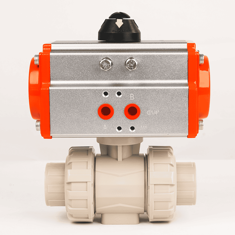
This is also where the true union design earns its place. Because the valve unscrews from its end connectors, it can be removed for service or replacement without cutting pipe — which is why it is the default body style for chemical dosing, water treatment, and skid-mounted systems. You can see the full range on our true union ball valve page. For larger-bore or higher-pressure lines, a flanged body is the alternative.
Step 3: Choose the actuator — double-acting or spring-return
This is the “pneumatic” half of the valve, and the first actuator decision is the action type.
- Double-acting (DA): air opens the valve and air closes it. It is the most economical and most common choice, and the right default when there is a reliable air supply and no fail-safe requirement.
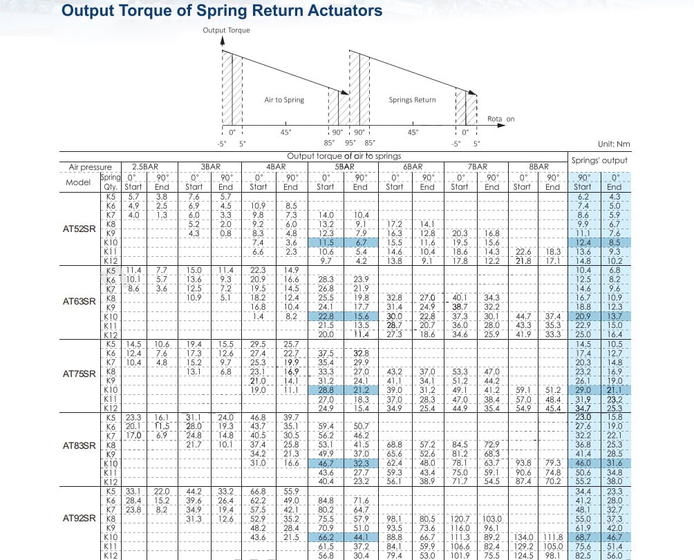
- Spring-return (SR): air drives the valve one way, and an internal spring returns it to a safe position if air or power is lost. Specify fail-close (normally closed) or fail-open (normally open) according to which state is safe for your process. SR is the choice for any safety-critical or emergency-shutdown duty.
Confirm the air supply pressure available on site as well; standard actuators are designed around 5–7 bar of clean, dry compressed air.
A sizing trap worth flagging early: a spring-return actuator is usually one to two sizes larger and heavier than a double-acting actuator of the same torque, because of the heavy spring pack inside. On tight or congested pipework, check the physical envelope of the SR actuator before you commit — we have seen correctly-specified valves that simply would not fit the space.
You can compare double-acting and spring-return versions across materials on our pneumatic true union ball valve pages: PVDF, CPVC, PPH, and UPVC.
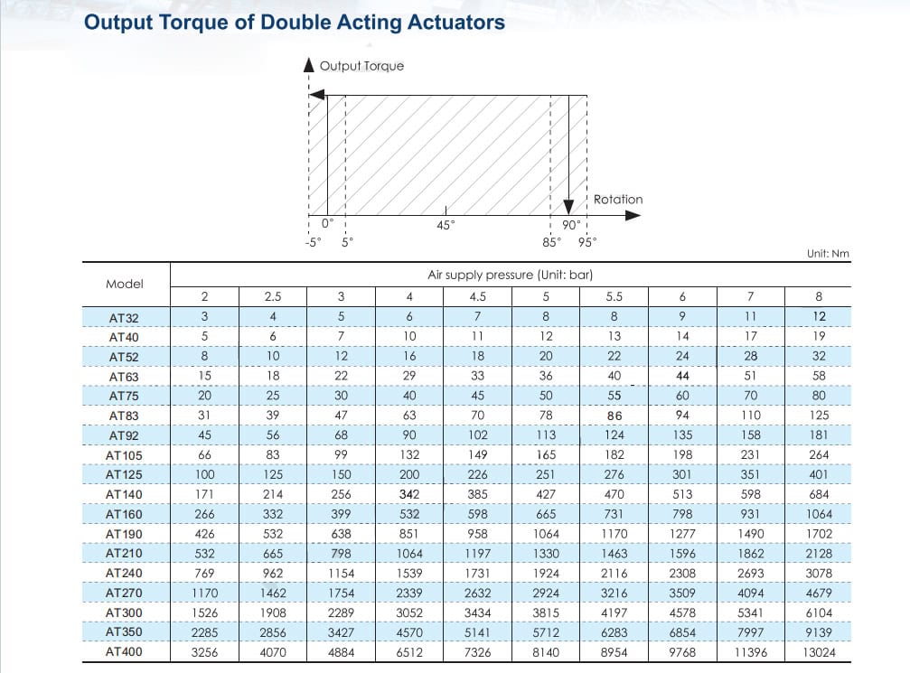
Step 4: Size the actuator — torque and safety factor
The single most common failure our engineers are called in to diagnose is an undersized actuator. The valve works on the test bench, then stalls in service once friction, media, and time are added.
The rule we size to:
| Service condition | Minimum actuator-to-valve torque ratio |
|---|---|
| Normal, clean media (water, dilute chemicals) | 1.3 – 1.5× the valve break torque (30–50% safety margin) |
| Strong alkali, caustic soda, crystallizing or high-viscosity media (chlor-alkali, pickling lines) | 1.8 – 2.0× the valve break torque |
The second row is the one that catches people out. With caustic, crystallizing, or viscous media, solids can build up on the seat and the break torque spikes well above the catalogue figure. If the actuator was sized at 1.3× for “normal” service, it will not pull the ball free — and within a few months it stalls, overheats, or seizes. On those duties we deliberately oversize to 1.8–2.0×.
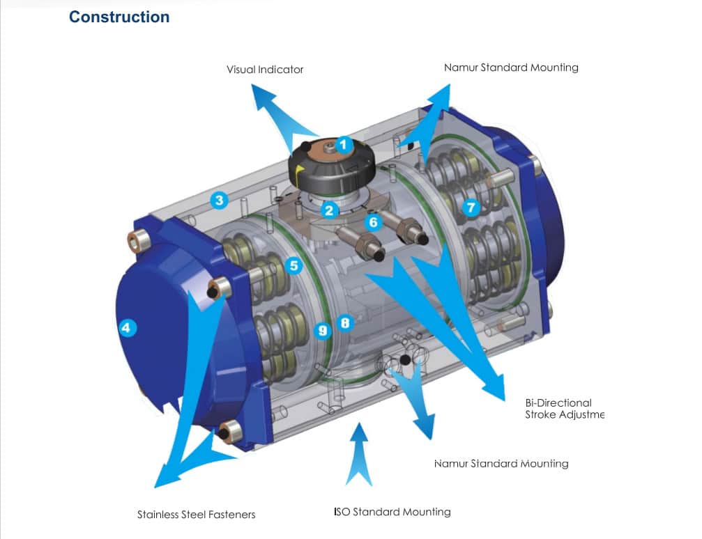
The actuators we fit are built to take that duty: rack-and-pinion, 90° quarter-turn, hard-anodised aluminium housing, IP67 protection, ISO 5211 / DIN 3337 / Namur interfaces, and a service life of ≥4 million cycles, maintenance-free. They are available double-acting or spring-return and carry 3C and SIL certification.
Step 5: Specify the control accessories
The final step matches the valve to your automation system (DCS/PLC). What you add depends on whether the valve is on/off or modulating:
- On-off control: add a solenoid valve — specify the coil voltage (24 VDC, 110 VAC, or 220 VAC) — and a limit switch box for position feedback (mechanical or proximity type).
- Modulating control: add an electro-pneumatic positioner that accepts a 4–20 mA signal to control the opening percentage.
- Always recommended: an air filter regulator (FRL) to keep the air supply clean and dry. It is a small line item that materially extends actuator life.
- Optional but useful: a manual override / handwheel so the valve can still be operated if air or power is lost.
Common pneumatic ball valve selection mistakes
Most field problems we see trace back to a short list of avoidable errors:
- Sizing the actuator for “normal” media on a crystallizing duty. Caustic and pickling services need the 1.8–2.0× factor, not 1.3×.
- Pairing EPDM with an aggressive medium (or with a PVDF body). The seal fails long before the body does.
- Reading the pressure rating without derating for temperature. PN10 cold is not PN10 hot.
- Mismatching the connection standard. A DIN socket will not accept ANSI or JIS pipe.
- Field-retrofitting a manual valve to pneumatic with a makeshift bracket. A non-integrated mount loosens as the actuator cycles, and the valve stops reaching full open or close. Use a factory-integrated assembly.
- Forgetting the spring-return envelope. SR actuators are bigger and heavier — confirm they fit before ordering.
How we build our pneumatic ball valves
Several of those failure modes are designed out of our valves rather than left to the installer:
- Integral ISO 5211 mounting platform. The actuator mounts directly to the valve with no separate bracket, so there is nothing to work loose and no extra potential leak points — the opposite of a field-fabricated conversion.
- PTFE seat. Chosen specifically to handle frequent cycling without developing the seat-wear leaks that plague softer materials.
- 304 stainless steel stem for corrosion resistance, and branded virgin resin throughout for traceable, consistent quality.
- Full configurability: UPVC, CPVC, PPH, or PVDF bodies; EPDM or FKM seals; ANSI, DIN, or JIS connections; sizes from DN15–DN100 (1/2″–4″), rated PN10.
Because we are a factory-direct manufacturer, we can supply OEM, project, and distributor quantities with custom configurations, a low MOQ of 20 pieces, and short lead times. Our main markets are Southeast Asia and South America, and we stock to both ANSI and DIN standards.
Field examples
Indonesia — copper smelter. After switching from PTFE-lined carbon steel pipe to a CPVC piping system, the plant cut installation cost by 38% and reduced maintenance by roughly ¥100,000 per kilometre per year. Our CPVC pneumatic double-acting ball valves have run on that system for over three years and more than 10,000 open/close cycles with zero leaks.
Vietnam — lithium battery plant. The site initially used a locally-supplied manual PPH true union ball valve that had been converted to pneumatic operation. It leaked within a month. Our engineers found two problems: the seal was EPDM, which is only suitable for ordinary water service, and the makeshift steel bracket was unstable, so the actuator worked loose after cycling and could no longer reach full position. After switching to our integrated industrial PPH pneumatic ball valve, the line has run without leaks since.
Pneumatic ball valve selection checklist
Use this checklist when you brief us — it is exactly the information our engineers need to specify the right valve and actuator the first time.
1. Line and media specifications
- Media (name and concentration): _______
- Working temperature: ____ °C min / ____ °C max
- Working pressure: ____ bar / PSI
2. Valve specifications
- Valve size: DN____ / ____ inch
- Body material: UPVC / CPVC / PPH / PVDF
- O-ring seal: EPDM / FKM (Viton)
- Connection standard: DIN (metric) / ANSI (ASTM) / JIS
- Connection type: socket weld / female thread
3. Actuator and control specifications
- Actuator action: double-acting / spring-return
- If spring-return: fail-close / fail-open
- Available air supply pressure: ____ bar / PSI
4. Accessories required
- Solenoid valve — voltage: 24 VDC / 110 VAC / 220 VAC
- Limit switch box — mechanical / proximity
- Positioner — 4–20 mA / smart
- Air filter regulator
- Manual override (handwheel)
Send us the completed checklist and our engineers will recommend the right valve and actuator for your application. Request a quote.
Written by Andy Xia, Huiya Engineering Team — 5 years in industrial piping and valves.